Showing posts with label to. Show all posts

Thursday, 11 April 2013

Cheap 12V to 220V Inverter

Even though today’s electrical appliances are increasingly often self-powered, especially the portable ones you carry around when camping or holidaying in summer, you do still sometimes need a source of 230 V AC - and while we’re about it, why not at a frequency close to that of the mains? As long as the power required from such a source remains relatively low - here we’ve chosen 30 VA - it’s very easy to build an inverter with simple, cheap components that many electronics hobbyists may even already have.

Though it is possible to build a more powerful circuit, the complexity caused by the very heavy currents to be handled on the low-voltage side leads to circuits that would be out of place in this summer issue. Let’s not forget, for example, that just to get a meager 1 amp at 230 VAC, the battery primary side would have to handle more than 20 ADC!. The circuit diagram of our project is easy to follow. A classic 555 timer chip, identified as IC1, is configured as an astable multivibrator at a frequency close to 100 Hz, which can be adjusted accurately by means of potentiometer P1.

Cheap 12V to 220V Inverter Circuit diagram:


As the mark/space ratio (duty factor) of the 555 output is a long way from being 1:1 (50%), it is used to drive a D-type flip-flop produced using a CMOS type 4013 IC. This produces perfect complementary square-wave signals (i.e. in antiphase) on its Q and Q outputs suitable for driving the output power transistors. As the output current available from the CMOS 4013 is very small, Darlington power transistors are used to arrive at the necessary output current. We have chosen MJ3001s from the now defunct Motorola (only as a semi-conductor manufacturer, of course!) which are cheap and readily available, but any equivalent power Darlington could be used.

These drive a 230 V to 2 × 9 V center-tapped transformer used ‘backwards’ to produce the 230 V output. The presence of the 230 VAC voltage is indicated by a neon light, while a VDR (voltage dependent resistor) type S10K250 or S07K250 clips off the spikes and surges that may appear at the transistor switching points. The output signal this circuit produces is approximately a square wave; only approximately, since it is somewhat distorted by passing through the transformer. Fortunately, it is suitable for the majority of electrical devices it is capable of supplying, whether they be light bulbs, small motors, or power supplies for electronic devices.

PCB layout:
pcb-layout-12-volt-to-230-volt-invertor-circuit-diagram
PCB Layout For Cheap 12V to 220V Inverter Circuit Diagram

Parts List :
Resistors
R1 = 18k?
R2 = 3k3
R3 = 1k
R4,R5 = 1k?5
R6 = VDR S10K250 (or S07K250)
P1 = 100 k potentiometer
Capacitors
C1 = 330nF
C2 = 1000 µF 25V
Semiconductor
T1,T2 = MJ3001
IC1 = 555
IC2 = 4013
Miscellaneous
LA1 = neon light 230 V
F1 = fuse, 5A
TR1 = mains transformer, 2x9V 40VA (see text)
4 solder pins
Note that, even though the circuit is intended and designed for powering by a car battery, i.e. from 12 V, the transformer is specified with a 9 V primary. But at full power you need to allow for a voltage drop of around 3 V between the collector and emitter of the power transistors. This relatively high saturation voltage is in fact a ‘shortcoming’ common to all devices in Darlington configuration, which actually consists of two transistors in one case. We’re suggesting a PCB design to make it easy to construct this project; as the component overlay shows, the PCB only carries the low-power, low-voltage components.

The Darlington transistors should be fitted onto a finned anodized aluminum heat-sink using the standard insulating accessories of mica washers and shouldered washers, as their collectors are connected to the metal cans and would otherwise be short-circuited. An output power of 30 VA implies a current consumption of the order of 3 A from the 12 V battery at the ‘primary side’. So the wires connecting the collectors of the MJ3001s [1] T1 and T2 to the transformer primary, the emitters of T1 and T2 to the battery negative terminal, and the battery positive terminal to the transformer primary will need to have a minimum cross-sectional area of 2 mm2 so as to minimize voltage drop.

The transformer can be any 230 V to 2 × 9 V type, with an E/I iron core or toroidal, rated at around 40 VA. Properly constructed on the board shown here, the circuit should work at once, the only adjustment being to set the output to a frequency of 50 Hz with P1. You should keep in minds that the frequency stability of the 555 is fairly poor by today’s standards, so you shouldn’t rely on it to drive your radio-alarm correctly – but is such a device very useful or indeed desirable to have on holiday anyway? Watch out too for the fact that the output voltage of this inverter is just as dangerous as the mains from your domestic power sockets.

So you need to apply just the same safety rules! Also, the project should be enclosed in a sturdy ABS or diecast so no parts can be touched while in operation. The circuit should not be too difficult to adapt to other mains voltages or frequencies, for example 110 V, 115 V or 127 V, 60 Hz. The AC voltage requires a transformer with a different primary voltage (which here becomes the secondary), and the frequency, some adjusting of P1 and possibly minor changes to the values of timing components R1 and C1 on the 555.

Source: http://www.ecircuitslab.com/2011/08/cheap-12v-to-220v-inverter.html
Read More..

Monday, 8 April 2013

Sound to Dancing Lights Converter Circuit


This is a design circuit for converting an audio signal (such as one that comes from the speaker terminals of a CD player). The circuit basically consists of a buffer/amplifier stage and three filter circuits: a high-pass filter, a mid-pass filter, and a low-pass filter. The output of each filter circuit drives a light-emitting diode of different color. This is the figure of the circuit;


The input signal is fed to the buffer stage through C1. The values of RF and RV1 should be chosen so that the buffer is able to drive the three filters attached to its output.  The low-frequency, mid-frequency, and high-frequency components of the input signal are only allowed to pass through the low-pass filter (bottom filter), the mid-pass filter (middle filter), and the high-pass filter (topmost filter), respectively, thus separating them from each other. Changes in the output of a filter cause its corresponding output LED to turn on and off.  In effect, feeding a continuous audio signal to the input of this circuit causes the LEDs to dance.
Read More..

Friday, 5 April 2013

How to check TV Flyback

There are actually several kinds of tools that can be used for check whether flybak damaged. But we have a simple way we have always done for ascertain whether flybak damaged or is still good, before replacing the horizontal transistor. All it takes is a light bulb with an added Exciter 100Watt cable connection along approximately 25cm.


The trick determine if flyback damaged or is still good is as follows :
How to check TV Flyback
  1. Break up the relationship between the collector of transistor horizontal flyback-out. By (a) Open collector aspirated by means of the printed board solder, or (b) Remove the jumper cables if any, or (b) Cutting prited path.
  2. Ac volt-meter pairs of horizontal transistor base with a ground out.
  3. Turn on the plane a little while - there must be an ac voltage of about 1v. This is done is for ensure that the horizontal oscillator and driver are working horizontally.
  4. Replace light bulb between the collector of transistor flyback horizontal (light diseri the collector).
  5. Turn on the plane while alternately measured heater voltage, screen (screen VR max).
  6. If no defective flyback voltage means. Usually marked with a light bulb that lights a little brighter.
  7. If the flyback is usually a good heater ac voltage is approximately 1 to 2v, screen voltage around 150v. Usually marked with a light bulb that lights dimmed.
  8. Measurements must be done quickly, because if the plane using circuit protectionism - protectionism will actively work then.
Defective flyback symptoms include:
  • Tr horizontal collapsed immediately replaced by new
  • B + voltage drops

Read More..

Thursday, 4 April 2013

Microcontroller to RS 485 circuit

Microcontroller to RS-485 circuit | RS-485 bus can carry up to 256 transceiver modules and over long distances . This is a circuit for connect microcontroller with Rs-485 bus.
Max485
Max485 are low-power transceivers for RS-485 and RS-422 communication. Each part contains one driver and one receiver. Line Length vs. Data Rate The RS-485/RS-422 standard covers line lengths up to 4000 feet. For line lengths greater than 4000 feet, see Typical Applications The MAX481, MAX483, MAX485, MAX487–MAX491, and MAX1487 transceivers are designed for bidirectional data communications on multipoint bus transmission lines.

Microcontroller to RS-485 circuit
Microcontroller to RS-485 circuit diagrams
Features
- In μMAX Package: Smallest 8-Pin SO
- Slew-Rate Limited for Error-Free Data Transmission
- 0.1μA Low-Current Shutdown Mode
- Low Quiescent Current
- -7V to +12V Common-Mode Input Voltage Range
- Three-State Outputs
- 30ns Propagation Delays, 5ns Skew
- Full-Duplex and Half-Duplex Versions Available
- Operate from a Single 5V Supply
- Allows up to 128 Transceivers on the Bus
- Current- Limiting and Thermal Shutdown for Driver Overload
Read More..

5 to 30 Minute Timer Circuit

A switched timer for intervals of 5 to 30 minutes incremented in 5 minute steps.


Simple to build, simple to make, nothing too complicated here. However you must use the CMOS type 555 timer designated the 7555, a normal 555 timer will not work here due to the resistor values. Also a low leakage type capacitor must be used for C1, and I would strongly suggest a Tantalum Bead type. Switch 3 adds an extra resistor in series to the timing chain with each rotation, the timing period us defined as


Timing = 1.1 C1 x R1

Note that R1 has a value of 8.2M with S3 at position "a" and 49.2M at position "f". This equates to just short of 300 seconds for each position of S3. C1 and R1 through R6 may be changed for different timing periods. The output current from Pin 3 of the timer, is amplified by Q1 and used to drive a relay. 

Parts List
Relay 9 volt coil with c/o contact (1)
S1: On/Off (1)
S2: Start (1)
S3: Range (1)
IC1: 7555 (1)
B1: 9V (1)
C1: 33uF CAP (1)
Q1: BC109C NPN (1)
D1: 1N4004 DIODE (1)
C2: 100n CAP (1)
R6,R5,R4,R3,R2,R1: 8.2M RESISTOR (6)
R8: 100k RESISTOR (1)
R7: 4.7k RESISTOR (1) 
Read More..

Tuesday, 2 April 2013

How to Installation A Car Stereo


Car Stereo Installation Guide - Want to save some money? Ever wonder if you could do a car stereo installation yourself? Yes, you can do it yourself! Go ahead, spend that money on your hardware! Don’t spend it on labor. Besides, doing a car stereo installation yourself can be a very rewarding experience, not to mention you can learn a lot from it too. Nothing beats the feeling of seeing your “creation” in action, running smoothly and perfectly.


Car Stereo Installation
But be very careful, you really won’t want to damage your expensive hardware. Well, most car audio hardware are no-brainers to install, you’d find that most of the time the parts have specially shaped sockets and slots etc. and would only fit where it’s supposed to be installed. Still, it’s best to proceed methodically.

In a car stereo installation, you have to determine what kind of rig you’re going to put into your vehicle. If you’re a beginner, it’s best you do a car stereo installation if it’s just a simple system. You may want to leave the complicated stuff to the professionals, like installing delicate equipment like LCD panels, motorized parts etc. especially if it requires the creation of custom panels and such. 

Head units are one of the easiest to do in a car stereo installation. Fortunately, most units follow the same size standards (DIN). In many cars, once the factory radio is removed the aftermarket radio will fit in the hole. In many other cars, a kit is needed if the factory hole is too big, or not deep enough. In some cases the dash has to be cut.  Any car stereo store should have kits required for installation. 

There are two types of mounting in a car stereo installation. ISO mounting is when the radio can be screwed to existing factory radio brackets, such as in most Japanese cars. Ring mounting is when an aftermarket radio comes with a metal ring that gets mounted to the factory radio hole or aftermarket kit via bendable tabs. In many cars, dash and trim rings have to be filed to enlarge the radio hole. Once the ring is installed, the radio slides in and is held by snaps. In most cases, special tools are required to remove the radio.

Speakers are very critical in a car stereo installation. No matter how expensive your speakers are, if they are not properly installed, the sound will not be up to par.

In a simple car stereo installation, you’ll probably be using speakers that fit into a factory location. Just make sure there are no gaps or holes. Sometimes building a wood or fiberglass baffle helps reduce holes and gives you much better sound. But always be careful when using power tools around speakers. Car stereo installation warranties usually dont cover holes in speakers.

For unconventional speaker locations, sometimes metal has to be cut. You might want to leave this to the professionals, tools like plasma cutters and pneumatics drills are required. But if you’re going to insist, a pair of metal snips (left and right cut) will do.

A car stereo installation has to put up with vibrations and other noise sources in its environment. Even though it is impossible to eliminate these completely, there are products that will greatly decrease the noise and rattling, particularly on non-luxury cars. Liners, sprays and adhesive strips and even carpeting applied onto the panels can make a world of difference.   

Read More..

Friday, 29 March 2013

Seven Segment Display Everything you need to know about

7 segment display  
Seven Segment display is the most common and fundamental display device which is used in many Electronic Gadgets and Appliances like Electric stove,Microwave Owen,Digital Clocks and also in many Digital Meters like Multimeter.

7-segments_Indicator-1-9

The seven segment display is called so since it contains 7 segments of LED which is assembled in a structure resembling like numeral ‘8’.This is because you can form all 10 digits (0-9) from the pattern ‘8’.
7segments
Actually 7 segment display consists on 8 segments,In which apart from seven segments mentioned above there is an extra segment to display dot,Which can be useful while displaying non integer number.
 

The 7 segments are named as A-G and the optional eighth segment is named as H.As you can see in the diagram the seven segment are arranged to form a shape of ‘8’.If all the segments are given the power then the number ‘8’ will be displayed and if you cutoff the power for segment G then it will result in number ‘0’.Similarly you can form the combinations to display numerals from 0 to 9.
Practically seven segment comes with two different configurations and both the type contains 10 pins.

The following are the two configurations of seven segment display

  1. Common Anode
  2. Common Cathode
7-sement-pin-config 
In Common Anode configuration the pin 3 and 8 are shorted together with Anode of all 8 LED segments and this common pin is connected to positive voltage (VCC).Hence to light up any given segment the corresponding Cathode pin should be connected to ground or reference ,which completes the circuit and LED will be in forward bias.
Similarly In Common Cathode configuration the pin 3 and 8 are shorted together with Cathode of all 8 LED segments and this common pin is connected to Ground or reference point.Here if you give positive voltage to corresponding LED Anode pin the the circuit will be completed and the particular LED will be light up since it will be in forward bias.
Note that if you are using Ground as reference voltage then your VCC should be greater than 1.3 V,Which is minimum voltage to light up LED based on silicon.(Bandgap Energy).
 common-anode-schematic

common-cathode-schematic

Need for series Resistors

Practically we always use the power source(VCC) as +5V or Higher so it is necessary to connect series resistor to the Anode pins (Common Cathode) or to Cathode Pins (Common Anode configuration).This will ensure that the LED doesn’t burn.
Here how the value of series resistor is determined
  • Forward bias voltage : +2V
  • Forward bias current : 20mA
Resistor value(ohm)=(Vcc – 2)/0.02  ohms
for example if you are using +5 V then Resistor value=(5-2)/0.02=150 ohms.
Nowadays the usage seven segment displays are very limit due to the advancement in display technologies,Now Dot matrix display mostly displaced the place of seven segment displays but yet seven segment displays are good starting point to read about display technologies.
7-segments_Indicator


Bonus fact

Actually you can display all Hexadecimal using seven segment display,that is apart from digits 0-9 it is also possible to show A,b,C,d,E,F.Now I leave this part to you,Why the alphabet ‘b’ and ‘d’ is not represented in caps ???
Read More..

Thursday, 28 March 2013

10 to 14W Class A Audio Amplifier

I have built this amplifier and it does sound good. It requires a preamp as it hasnt got much gain. It requires big heat sinks and a large transformer and a great power supply and careful wiring, but in the end it is xtremely simple and it sounds very good. The zener diode rejects any ripple coming from the power supply, But you still only want a ripple of 10mV max. The ripple reaching the input is amplified, so the zener diode gets rid of that, but whatever ripple there is will still reach the power stage.

10 to 14W Class A Audio Amplifier
Read More..

Wednesday, 27 March 2013

How to Make a LED Chaser cum Blinker Circuit Using IC 4017


  The presented circuit was requested by Mr.Joe, one of the keen followers of this blog. The circuit initially was intended to be used for generating LED strobe light effects and was asked to be modified such that it could be used as an LED sequencer as well as a blinker. The change over would be implemented via a toggle switch.

The circuit diagram may be understood with the following points:

The IC 4017 is not new to us and we all know how versatile and competent this device is. Basically the IC a Johnson’s decade counter/divide by 10 IC, fundamentally used in applications where sequencing positive output signals are required or desired.

 The sequencing or the orderly shifting of the outputs take place in response to a clock pulse that needs to be applied at the clock input pin #14 of the IC.

With every rising positive edge of the clock input, the IC responds and pushes its output’s positive from the existing pin out to the next pin out in the order.

Here a couple of NOT gates are used as a oscillator for providing the above clock pulses to the IC 4017. VR1 may be adjuted for determining or fixing the speed of the sequencing.

The outputs of the IC are connected to an array of LEDs in a specific order which makes the LEDs look like as if they are running or chasing during the operations.

If the circuit would be required only to produce the chasing effect, the diodes would not be required, however as per the present ask the diodes become important and allows the circuit to be used as a blinker also, depending upon the position of the switch S1.

When the switch S1 is positioned at A, the circuit behaves like a light chaser and produces the normal chasing effect over the LEDs which start illuminating in sequence from top to the bottom, repeating the operations as long as the circuit remains powered.

As soon as S1 is flicked toward B, the clock signals from the oscillator are shifted into the input of the transistor T1, which instantly stats to pulsate all the LEDs together in response to the received clocks from N1/N2 configuration.

Thus as per the requirement we have successfully modified an ordinary light chaser circuit with an additional feature through which the circuit now is also able to function as a LED flasher.

Do not forget to connect the inputs of the remaining unused gates from the IC 4049 either to the positive or the negative of the supply. The supply pins of the IC 4049 also need to be connected to the relevant supply rails of the circuit, kindly refer to the datasheet of the IC.

Tf all the ten outputs of the IC 4017 are required to be integrated with LED sequencing, just connect pin #15 of the IC to ground and use the left over outputs of the IC for the required sequencing of the LEDs in the order of: 3,2,4,7,10,1,5,6,9,11

Parts List

The fooliwng parts will be needed for making this LED light chaser cum flaher circuit:

R1, R2, R3 = 1K,
VR1 = 100K linear pot.
All LED resistors are = 470 Ohms,
All diodes are = 1N4148,
All LEDs = RED, 5mm or as per choice,
T1 = 2N2907, or 8550 or 187,
C1 = 10uF/25V
C2 = 0.1uF,
IC1 = 4017,
N1, N2 = IC4049
Read More..

Monday, 25 March 2013

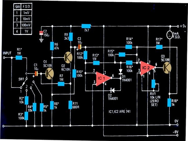
How to Measure AC Milli volts Using IC 741 Circuit Diagram


The circuit shown below can be used to measure DC potentials in the range of milli-volts. The circuit is highly sensitive and is calibrated to measure voltages in the range of  1 mV minimum to 1 V maximum.


Measuring potentials in the order of milli-volts is generally difficult using ordinary multimeters. The circuit shown here can be used for sensing minute AC signals in the range of as low as 0.1 mV.

The transistors Q1 and Q2 has been configured as high gain feedback kind of amplifier, with the shown components the amplifier stage has been foxed to produce a gain of 100.

The next stage which consists of  two 741 ICs, IC1 and IC2, have been wired up as precision rectifiers.
These together are able to generate a gain of 10 over bandwidth that might extend above 50kHz or below 20 Hz.

The over all gain of the circuit therefore falls in the range of 1000, which makes it imperative to have signals below 1mV well attenuated.
The setting of the circuit does not involve much of complication, just the preset RV1 needs to be adjusted initially for making the connected meter show a zero when there no signal at the input.

All resistors marked with asterisk must be 1% rated, MFR types.


Read More..