Showing posts with label timer. Show all posts
Showing posts with label timer. Show all posts
Tuesday, 14 May 2013
Long duration timer circuit
 This timer circuit can be used to switch OFF a particular device after around 35 minutes. The circuit can be used to switch OFF devices like radio, TV, fan, pump etc after a preset time of 35 minutes. Such a circuit can surely save a lot of power.

Thursday, 4 April 2013
5 to 30 Minute Timer Circuit
A switched timer for intervals of 5 to 30 minutes incremented in 5 minute steps.
 Simple to build, simple to make, nothing too complicated here. However you must use the CMOS type 555 timer designated the 7555, a normal 555 timer will not work here due to the resistor values. Also a low leakage type capacitor must be used for C1, and I would strongly suggest a Tantalum Bead type. Switch 3 adds an extra resistor in series to the timing chain with each rotation, the timing period us defined as
Note that R1 has a value of 8.2M with S3 at position "a" and 49.2M at position "f". This equates to just short of 300 seconds for each position of S3. C1 and R1 through R6 may be changed for different timing periods. The output current from Pin 3 of the timer, is amplified by Q1 and used to drive a relay.

Timing = 1.1 C1 x R1
Parts List
Relay 9 volt coil with c/o contact (1)
S1: On/Off (1)
S2: Start (1)
S3: Range (1)
IC1: 7555 (1)
B1: 9V (1)
C1: 33uF CAP (1)
Q1: BC109C NPN (1)
D1: 1N4004 DIODE (1)
C2: 100n CAP (1)
R6,R5,R4,R3,R2,R1: 8.2M RESISTOR (6)
R8: 100k RESISTOR (1)
R7: 4.7k RESISTOR (1) Relay 9 volt coil with c/o contact (1)
S1: On/Off (1)
S2: Start (1)
S3: Range (1)
IC1: 7555 (1)
B1: 9V (1)
C1: 33uF CAP (1)
Q1: BC109C NPN (1)
D1: 1N4004 DIODE (1)
C2: 100n CAP (1)
R6,R5,R4,R3,R2,R1: 8.2M RESISTOR (6)
R8: 100k RESISTOR (1)
Monday, 25 March 2013
Amplifier Timer Circuit Diagram
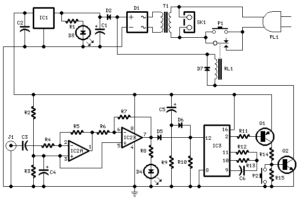
This circuit turns-off an amplifier or any other device when a low level audio signal fed to its input is absent for 15 minutes at least. Pushing P1 the device is switched-on feeding any appliance connected to SK1. Input audio signal is boosted and squared by IC2A & IC2B and monitored by LED D4.
When D4 illuminates, albeit for any fairly short peak, IC3 is reset and restarts its counting. Pin 2 of IC3 is still at the low state, the two transistors seem like on too as the relay operates. When, after a 15 minutes delay, no signal appeared at the input, IC3 ends its counting and pin 2 will go high. Q1 & Q2 stop conducting too as the relay switches-off. The device is thus totally off too seem like the appliances connected to SK1. C5 & R9 reset IC3 at power-on. P2 allows switch-off at any moment.
When D4 illuminates, albeit for any fairly short peak, IC3 is reset and restarts its counting. Pin 2 of IC3 is still at the low state, the two transistors seem like on too as the relay operates. When, after a 15 minutes delay, no signal appeared at the input, IC3 ends its counting and pin 2 will go high. Q1 & Q2 stop conducting too as the relay switches-off. The device is thus totally off too seem like the appliances connected to SK1. C5 & R9 reset IC3 at power-on. P2 allows switch-off at any moment.
Sunday, 24 March 2013
Automatic Door Lamp Timer Circuit
The article explains a simple automatic door light timer circuit which activates every time the door is opened, and switches OFF after a predetermined time if the door is kept open for too long. The circuit was requested by one of the avid readers of this blog, Mr. Juan. Lets learn more.
The request:
I always find your bolg very interesting.
I want to know if this would be possible
I have a cabinet in with I put a magnetic switch with normally closed and normally open contacts. (today, I only use one of them)
Today, when you open the door, the light that is on top turns on
I would change the circuit so that:
1. Open the door once so the circuit is ON, after a given time, the light turns off (although the door hasnt been closed and is opened). If I ever want to turn on the light, I have to close the door and reopen it.
2. add a LDR to turn on the light ONLY if there isnt sunlight in the room. With LDR in series with the load is enough?
The system is 12V. Should I use the famous 555? (all Ive seen is with tiggers (push buttons), which is not my case)
Thank you.
The Design
Instead of 555 IC, a 4060 IC has been used here due to its better accuracy.
The IC 4060 is configured in its standard delay timer mode, where the 1M pot and 0.68uF decides the length of the time delay.

The request:
I always find your bolg very interesting.
I want to know if this would be possible
I have a cabinet in with I put a magnetic switch with normally closed and normally open contacts. (today, I only use one of them)
Today, when you open the door, the light that is on top turns on
I would change the circuit so that:
1. Open the door once so the circuit is ON, after a given time, the light turns off (although the door hasnt been closed and is opened). If I ever want to turn on the light, I have to close the door and reopen it.
2. add a LDR to turn on the light ONLY if there isnt sunlight in the room. With LDR in series with the load is enough?
The system is 12V. Should I use the famous 555? (all Ive seen is with tiggers (push buttons), which is not my case)
Thank you.
The Design
Instead of 555 IC, a 4060 IC has been used here due to its better accuracy.
The IC 4060 is configured in its standard delay timer mode, where the 1M pot and 0.68uF decides the length of the time delay.
The door switch is set in such a way that it closes when the door opens.
The 10uF capactor at the supply resets pin#16 so that the timer initiates the counting process from zero.
During this period pin#3 stays at logic zero, keeping the first BC547 switched off, which in turn switches ON the relay driver and the lamp.
If the door stays open until the timer delay lapses, pin#3 goes high switching ON the first BC547 and consequently switching OFF the relay driver and the lamp.
Also, at the same time the positive from pin#3 reaches pin#11 of the IC via the connected 1N4148 diode which latches the entire circuit.
This renders the lamp permanently ON,
In order to switch OFF the lamp, the door will need to be closed now.
An LDR at the base of the first transistor makes sure that this transistor switches ON when theres ample ambient light.
In the above situation the relay driver transistor is held switched OFF, which in turn keeps the lamp switched OFF.
Subscribe to:
Posts (Atom)
