Showing posts with label ic. Show all posts

Friday, 17 May 2013

Car Subwoofer filter using OP Amp IC TL072

Car Subwoofer filter using OP Amp IC TL072

Here is the circuit diagram of simple and easy subwoofer filter which will be operated from a 12V DC supply. Such a circuit is incredibly helpful in Car subwoofer applications. The circuit is nothing however a low pass filter whose pass frequency will be adjusted between 60 to 160 Hz.


The circuit is intended round the TL072 twin BIFET opamp IC. Out of the 2 opamps within the chip, IC1A is wired as a buffer. The left and right audio inputs when mixing is fed to the input of the IC1A using the DPDT switch S1. Switch S1 is that the section control switch which might be used to create the subwoofer in section with different speakers.


When S1 is in position {2, 180 degree phase shift are induced.POT R7 will be used for controlling the level. IC1B forms the low pass filter whose pass frequency will be controlled by adjusting the twin gang POT R13.

Read More..

Monday, 13 May 2013

One IC two tones Siren

Siren circuit diagramThis circuit is intended for children fun, and can be installed on bicycles, battery powered cars and motorcycles, but also on models and various games and toys.

With SW1 positioned as shown in the circuit diagram, the typical dual-tone sound of Police or Fire-brigade cars is generated, by the oscillation of IC1A and IC1B gates. With SW1 set to the other position, the old siren sound increasing in frequency and then slowly decreasing is reproduced, by pushing on P1 that starts oscillation in IC1C and IC1D.
The loudspeaker, driven by Q1, should be of reasonable dimensions and well encased, in order to obtain a more realistic and louder output. Tone and period of the sound oscillations can be varied by changing the values of C1, C2, C5, C6 and/or associated resistors. No power switch is required: leave SW1 in the low position (old-type siren) and the circuit consumption will be negligible.

Parts:

R1,R3___470K 1/4W Resistors
R2______680K 1/4W Resistor
R4_______82K 1/4W Resistor
R5______330K 1/4W Resistor
R6_______10K 1/4W Resistor
R7_______33K 1/4W Resistor
R8________3M3 1/4W Resistor

C1,C5_____10µF 25V Electrolytic Capacitors
C2,C6_____10nF 63V Polyester Capacitors
C3_______100nF 63V Polyester Capacitor
C4_______100µF 25V Electrolytic Capacitor

D1-D3___1N4148 75V 150mA Diodes

IC1_____4093 Quad 2 input Schmitt NAND Gate IC

Q1______BC337 45V 800mA NPN Transistor

P1______SPST Pushbutton

SW1_____DPDT Switch

SPKR____8 Ohm Loudspeaker

B1______6V Battery (4 AA 1.5V Cells in series)

Read More..

Wednesday, 10 April 2013

Basic IC MonoStable Multivibrator


Basic LM555 Timer CIRCUIT

Part List
C2 = .01uf
IC1 = LM555 Timer
SWI = n.o. momentary switch
R1 and C1 determine lenght of
out put pulse where  t = R1 x C1
and R1 is in ohms and C1 is in farads .

by Tony van Roon
Read More..

Wednesday, 27 March 2013

How to Make a LED Chaser cum Blinker Circuit Using IC 4017


  The presented circuit was requested by Mr.Joe, one of the keen followers of this blog. The circuit initially was intended to be used for generating LED strobe light effects and was asked to be modified such that it could be used as an LED sequencer as well as a blinker. The change over would be implemented via a toggle switch.

The circuit diagram may be understood with the following points:

The IC 4017 is not new to us and we all know how versatile and competent this device is. Basically the IC a Johnson’s decade counter/divide by 10 IC, fundamentally used in applications where sequencing positive output signals are required or desired.

 The sequencing or the orderly shifting of the outputs take place in response to a clock pulse that needs to be applied at the clock input pin #14 of the IC.

With every rising positive edge of the clock input, the IC responds and pushes its output’s positive from the existing pin out to the next pin out in the order.

Here a couple of NOT gates are used as a oscillator for providing the above clock pulses to the IC 4017. VR1 may be adjuted for determining or fixing the speed of the sequencing.

The outputs of the IC are connected to an array of LEDs in a specific order which makes the LEDs look like as if they are running or chasing during the operations.

If the circuit would be required only to produce the chasing effect, the diodes would not be required, however as per the present ask the diodes become important and allows the circuit to be used as a blinker also, depending upon the position of the switch S1.

When the switch S1 is positioned at A, the circuit behaves like a light chaser and produces the normal chasing effect over the LEDs which start illuminating in sequence from top to the bottom, repeating the operations as long as the circuit remains powered.

As soon as S1 is flicked toward B, the clock signals from the oscillator are shifted into the input of the transistor T1, which instantly stats to pulsate all the LEDs together in response to the received clocks from N1/N2 configuration.

Thus as per the requirement we have successfully modified an ordinary light chaser circuit with an additional feature through which the circuit now is also able to function as a LED flasher.

Do not forget to connect the inputs of the remaining unused gates from the IC 4049 either to the positive or the negative of the supply. The supply pins of the IC 4049 also need to be connected to the relevant supply rails of the circuit, kindly refer to the datasheet of the IC.

Tf all the ten outputs of the IC 4017 are required to be integrated with LED sequencing, just connect pin #15 of the IC to ground and use the left over outputs of the IC for the required sequencing of the LEDs in the order of: 3,2,4,7,10,1,5,6,9,11

Parts List

The fooliwng parts will be needed for making this LED light chaser cum flaher circuit:

R1, R2, R3 = 1K,
VR1 = 100K linear pot.
All LED resistors are = 470 Ohms,
All diodes are = 1N4148,
All LEDs = RED, 5mm or as per choice,
T1 = 2N2907, or 8550 or 187,
C1 = 10uF/25V
C2 = 0.1uF,
IC1 = 4017,
N1, N2 = IC4049
Read More..

Monday, 25 March 2013

How to Measure AC Milli volts Using IC 741 Circuit Diagram


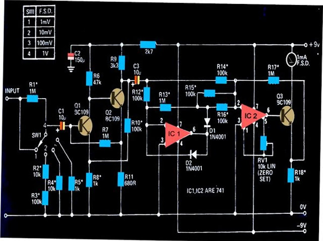
The circuit shown below can be used to measure DC potentials in the range of milli-volts. The circuit is highly sensitive and is calibrated to measure voltages in the range of  1 mV minimum to 1 V maximum.


Measuring potentials in the order of milli-volts is generally difficult using ordinary multimeters. The circuit shown here can be used for sensing minute AC signals in the range of as low as 0.1 mV.

The transistors Q1 and Q2 has been configured as high gain feedback kind of amplifier, with the shown components the amplifier stage has been foxed to produce a gain of 100.

The next stage which consists of  two 741 ICs, IC1 and IC2, have been wired up as precision rectifiers.
These together are able to generate a gain of 10 over bandwidth that might extend above 50kHz or below 20 Hz.

The over all gain of the circuit therefore falls in the range of 1000, which makes it imperative to have signals below 1mV well attenuated.
The setting of the circuit does not involve much of complication, just the preset RV1 needs to be adjusted initially for making the connected meter show a zero when there no signal at the input.

All resistors marked with asterisk must be 1% rated, MFR types.


Read More..