Showing posts with label how. Show all posts
Showing posts with label how. Show all posts
Friday, 5 April 2013
How to check TV Flyback
There are actually several kinds of tools that can be used for check whether flybak damaged. But we have a simple way we have always done for ascertain whether flybak damaged or is still good, before replacing the horizontal transistor. All it takes is a light bulb with an added Exciter 100Watt cable connection along approximately 25cm.
The trick determine if flyback damaged or is still good is as follows :

- Break up the relationship between the collector of transistor horizontal flyback-out. By (a) Open collector aspirated by means of the printed board solder, or (b) Remove the jumper cables if any, or (b) Cutting prited path.
- Ac volt-meter pairs of horizontal transistor base with a ground out.
- Turn on the plane a little while - there must be an ac voltage of about 1v. This is done is for ensure that the horizontal oscillator and driver are working horizontally.
- Replace light bulb between the collector of transistor flyback horizontal (light diseri the collector).
- Turn on the plane while alternately measured heater voltage, screen (screen VR max).
- If no defective flyback voltage means. Usually marked with a light bulb that lights a little brighter.
- If the flyback is usually a good heater ac voltage is approximately 1 to 2v, screen voltage around 150v. Usually marked with a light bulb that lights dimmed.
- Measurements must be done quickly, because if the plane using circuit protectionism - protectionism will actively work then.
Defective flyback symptoms include:
- Tr horizontal collapsed immediately replaced by new
- B + voltage drops
Tuesday, 2 April 2013
How to Installation A Car Stereo
Car Stereo Installation Guide - Want to save some money? Ever wonder if you could do a car stereo installation yourself? Yes, you can do it yourself! Go ahead, spend that money on your hardware! Don’t spend it on labor. Besides, doing a car stereo installation yourself can be a very rewarding experience, not to mention you can learn a lot from it too. Nothing beats the feeling of seeing your “creation” in action, running smoothly and perfectly.

But be very careful, you really won’t want to damage your expensive hardware. Well, most car audio hardware are no-brainers to install, you’d find that most of the time the parts have specially shaped sockets and slots etc. and would only fit where it’s supposed to be installed. Still, it’s best to proceed methodically.
In a car stereo installation, you have to determine what kind of rig you’re going to put into your vehicle. If you’re a beginner, it’s best you do a car stereo installation if it’s just a simple system. You may want to leave the complicated stuff to the professionals, like installing delicate equipment like LCD panels, motorized parts etc. especially if it requires the creation of custom panels and such.
Head units are one of the easiest to do in a car stereo installation. Fortunately, most units follow the same size standards (DIN). In many cars, once the factory radio is removed the aftermarket radio will fit in the hole. In many other cars, a kit is needed if the factory hole is too big, or not deep enough. In some cases the dash has to be cut. Any car stereo store should have kits required for installation.
There are two types of mounting in a car stereo installation. ISO mounting is when the radio can be screwed to existing factory radio brackets, such as in most Japanese cars. Ring mounting is when an aftermarket radio comes with a metal ring that gets mounted to the factory radio hole or aftermarket kit via bendable tabs. In many cars, dash and trim rings have to be filed to enlarge the radio hole. Once the ring is installed, the radio slides in and is held by snaps. In most cases, special tools are required to remove the radio.
Speakers are very critical in a car stereo installation. No matter how expensive your speakers are, if they are not properly installed, the sound will not be up to par.
In a simple car stereo installation, you’ll probably be using speakers that fit into a factory location. Just make sure there are no gaps or holes. Sometimes building a wood or fiberglass baffle helps reduce holes and gives you much better sound. But always be careful when using power tools around speakers. Car stereo installation warranties usually dont cover holes in speakers.
For unconventional speaker locations, sometimes metal has to be cut. You might want to leave this to the professionals, tools like plasma cutters and pneumatics drills are required. But if you’re going to insist, a pair of metal snips (left and right cut) will do.
A car stereo installation has to put up with vibrations and other noise sources in its environment. Even though it is impossible to eliminate these completely, there are products that will greatly decrease the noise and rattling, particularly on non-luxury cars. Liners, sprays and adhesive strips and even carpeting applied onto the panels can make a world of difference.
Wednesday, 27 March 2013
How to Make a LED Chaser cum Blinker Circuit Using IC 4017
The presented circuit was requested by Mr.Joe, one of the keen followers of this blog. The circuit initially was intended to be used for generating LED strobe light effects and was asked to be modified such that it could be used as an LED sequencer as well as a blinker. The change over would be implemented via a toggle switch.
The circuit diagram may be understood with the following points:
The IC 4017 is not new to us and we all know how versatile and competent this device is. Basically the IC a Johnson’s decade counter/divide by 10 IC, fundamentally used in applications where sequencing positive output signals are required or desired.
The sequencing or the orderly shifting of the outputs take place in response to a clock pulse that needs to be applied at the clock input pin #14 of the IC.
With every rising positive edge of the clock input, the IC responds and pushes its output’s positive from the existing pin out to the next pin out in the order.
Here a couple of NOT gates are used as a oscillator for providing the above clock pulses to the IC 4017. VR1 may be adjuted for determining or fixing the speed of the sequencing.
The outputs of the IC are connected to an array of LEDs in a specific order which makes the LEDs look like as if they are running or chasing during the operations.

If the circuit would be required only to produce the chasing effect, the diodes would not be required, however as per the present ask the diodes become important and allows the circuit to be used as a blinker also, depending upon the position of the switch S1.
When the switch S1 is positioned at A, the circuit behaves like a light chaser and produces the normal chasing effect over the LEDs which start illuminating in sequence from top to the bottom, repeating the operations as long as the circuit remains powered.
As soon as S1 is flicked toward B, the clock signals from the oscillator are shifted into the input of the transistor T1, which instantly stats to pulsate all the LEDs together in response to the received clocks from N1/N2 configuration.
Thus as per the requirement we have successfully modified an ordinary light chaser circuit with an additional feature through which the circuit now is also able to function as a LED flasher.
Do not forget to connect the inputs of the remaining unused gates from the IC 4049 either to the positive or the negative of the supply. The supply pins of the IC 4049 also need to be connected to the relevant supply rails of the circuit, kindly refer to the datasheet of the IC.
Tf all the ten outputs of the IC 4017 are required to be integrated with LED sequencing, just connect pin #15 of the IC to ground and use the left over outputs of the IC for the required sequencing of the LEDs in the order of: 3,2,4,7,10,1,5,6,9,11
Parts List
The fooliwng parts will be needed for making this LED light chaser cum flaher circuit:
R1, R2, R3 = 1K,
VR1 = 100K linear pot.
All LED resistors are = 470 Ohms,
All diodes are = 1N4148,
All LEDs = RED, 5mm or as per choice,
T1 = 2N2907, or 8550 or 187,
C1 = 10uF/25V
C2 = 0.1uF,
IC1 = 4017,
N1, N2 = IC4049
Monday, 25 March 2013
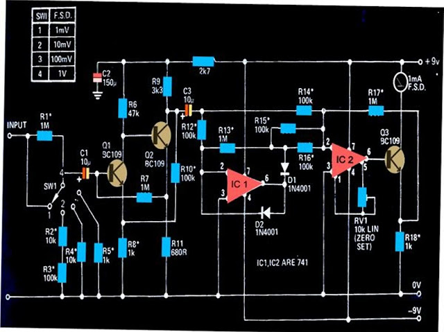
How to Measure AC Milli volts Using IC 741 Circuit Diagram
The circuit shown below can be used to measure DC potentials in the range of milli-volts. The circuit is highly sensitive and is calibrated to measure voltages in the range of 1 mV minimum to 1 V maximum.
Measuring potentials in the order of milli-volts is generally difficult using ordinary multimeters. The circuit shown here can be used for sensing minute AC signals in the range of as low as 0.1 mV.
The transistors Q1 and Q2 has been configured as high gain feedback kind of amplifier, with the shown components the amplifier stage has been foxed to produce a gain of 100.
The next stage which consists of two 741 ICs, IC1 and IC2, have been wired up as precision rectifiers.
These together are able to generate a gain of 10 over bandwidth that might extend above 50kHz or below 20 Hz.
The over all gain of the circuit therefore falls in the range of 1000, which makes it imperative to have signals below 1mV well attenuated.
The setting of the circuit does not involve much of complication, just the preset RV1 needs to be adjusted initially for making the connected meter show a zero when there no signal at the input.
All resistors marked with asterisk must be 1% rated, MFR types.
Subscribe to:
Posts (Atom)
