Showing posts with label ac. Show all posts
Showing posts with label ac. Show all posts
Wednesday, 12 June 2013
AC Motor Speed Controller Circuit With explanation
This AC motor speed controller can handle most universal type (brushed) AC motors and other loads up to about 250W. It works in much the same was a light dimmer circuit; by chopping part of the AC waveform off to effectively control voltage. Because of this functionality, the circuit will work for a wide variety of loads including incandescent light bulbs, heating elements, brushed AC motors and some transformers. The circuit tries to maintain a constant motor speed regardless of load so it is also ideal for power tools. Note that the circuit can only control brushed AC motors. Inductive motors require a variable frequency control. 
Read More..
Parts
| |
Notes |
- TR1 must be chosen to match the requirements of the load. Most generic TRIACs with ratings to support your load will work fine in this circuit. If you find a TRIAC that works well, feel free to leave a comment.
- U1 must be chosen to match the ratings of TR1. Most generic DIAC based opto-isolators will work fine. If you have success with a specific part, feel free to leave a comment.
- T1 is any small transformer with a 1:10 turns ratio. The circuit is designed to run on 120V so a 120V to 12V transformer will work. Alternately, you can wind T1 on a transformer core using a primary of 25 turns, a secondary of 200 turns, and 26 gauge magnet wire.
- R9 is used to adjust motor speed. R10 is a trim pot used to fine tune the governing action of the circuit. R8 fine tunes the feedback circuit to adjust for proper voltage at the gate of SCR1. It should be adjusted to just past the minimum point at which the circuit begins to operate.
- R13 must be chosen to match the load. Generally, larger loads will require a smaller value.
- Since this circuit is not isolated from mains, it must be built in an insulated case.

Monday, 25 March 2013
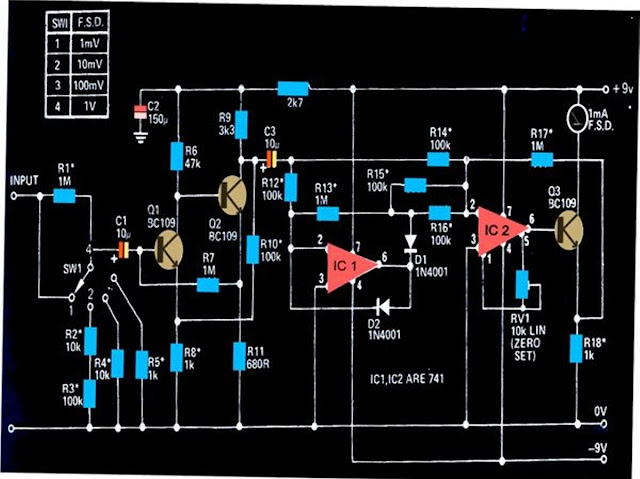
How to Measure AC Milli volts Using IC 741 Circuit Diagram
The circuit shown below can be used to measure DC potentials in the range of milli-volts. The circuit is highly sensitive and is calibrated to measure voltages in the range of 1 mV minimum to 1 V maximum.
Measuring potentials in the order of milli-volts is generally difficult using ordinary multimeters. The circuit shown here can be used for sensing minute AC signals in the range of as low as 0.1 mV.
The transistors Q1 and Q2 has been configured as high gain feedback kind of amplifier, with the shown components the amplifier stage has been foxed to produce a gain of 100.
The next stage which consists of two 741 ICs, IC1 and IC2, have been wired up as precision rectifiers.
These together are able to generate a gain of 10 over bandwidth that might extend above 50kHz or below 20 Hz.
The over all gain of the circuit therefore falls in the range of 1000, which makes it imperative to have signals below 1mV well attenuated.
The setting of the circuit does not involve much of complication, just the preset RV1 needs to be adjusted initially for making the connected meter show a zero when there no signal at the input.
All resistors marked with asterisk must be 1% rated, MFR types.
Subscribe to:
Posts (Atom)
