Monday, 25 March 2013
How to Measure AC Milli volts Using IC 741 Circuit Diagram
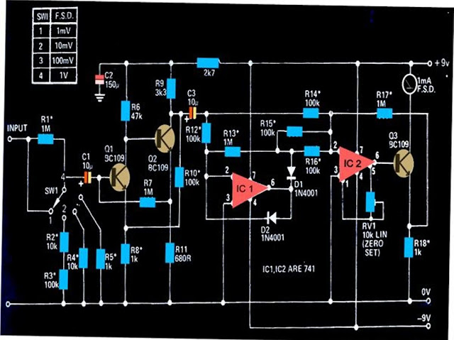
The circuit shown below can be used to measure DC potentials in the range of milli-volts. The circuit is highly sensitive and is calibrated to measure voltages in the range of 1 mV minimum to 1 V maximum.
Measuring potentials in the order of milli-volts is generally difficult using ordinary multimeters. The circuit shown here can be used for sensing minute AC signals in the range of as low as 0.1 mV.
The transistors Q1 and Q2 has been configured as high gain feedback kind of amplifier, with the shown components the amplifier stage has been foxed to produce a gain of 100.
The next stage which consists of two 741 ICs, IC1 and IC2, have been wired up as precision rectifiers.
These together are able to generate a gain of 10 over bandwidth that might extend above 50kHz or below 20 Hz.
The over all gain of the circuit therefore falls in the range of 1000, which makes it imperative to have signals below 1mV well attenuated.
The setting of the circuit does not involve much of complication, just the preset RV1 needs to be adjusted initially for making the connected meter show a zero when there no signal at the input.
All resistors marked with asterisk must be 1% rated, MFR types.
Subscribe to:
Post Comments (Atom)
No comments:
Post a Comment
Note: only a member of this blog may post a comment.