Wednesday 12 June 2013
AC Motor Speed Controller Circuit With explanation
This AC motor speed controller can handle most universal type (brushed) AC motors and other loads up to about 250W. It works in much the same was a light dimmer circuit; by chopping part of the AC waveform off to effectively control voltage. Because of this functionality, the circuit will work for a wide variety of loads including incandescent light bulbs, heating elements, brushed AC motors and some transformers. The circuit tries to maintain a constant motor speed regardless of load so it is also ideal for power tools. Note that the circuit can only control brushed AC motors. Inductive motors require a variable frequency control. 
Read More..
Parts
| |
Notes |
- TR1 must be chosen to match the requirements of the load. Most generic TRIACs with ratings to support your load will work fine in this circuit. If you find a TRIAC that works well, feel free to leave a comment.
- U1 must be chosen to match the ratings of TR1. Most generic DIAC based opto-isolators will work fine. If you have success with a specific part, feel free to leave a comment.
- T1 is any small transformer with a 1:10 turns ratio. The circuit is designed to run on 120V so a 120V to 12V transformer will work. Alternately, you can wind T1 on a transformer core using a primary of 25 turns, a secondary of 200 turns, and 26 gauge magnet wire.
- R9 is used to adjust motor speed. R10 is a trim pot used to fine tune the governing action of the circuit. R8 fine tunes the feedback circuit to adjust for proper voltage at the gate of SCR1. It should be adjusted to just past the minimum point at which the circuit begins to operate.
- R13 must be chosen to match the load. Generally, larger loads will require a smaller value.
- Since this circuit is not isolated from mains, it must be built in an insulated case.
Pin Led Light
PacMan Eat the Street Lamps
PAC-MAN game is very popular, you might like this creative gift - Pac-Man, his ghost enemies is in Geneva, Switzerland by artist Rafael on behalf of care Bufalino and Deseille.I can not imagine that the bulb is especially good, tasted all the good start but it does not like pixel point and power particles. Ghost. Blech! The Blinky determine a range of bottle (and cherries).
This is not the same, this is the first set of many years, I see Pac-Man inspired by light, but the clever use of these old Italian string lights things, like a spirit particles, so that these special, in my book.
PAC-MAN back to 2010 in December in Geneva, streets, trees and the Festival of Lights, I just see it now that is worth writing ... do you think?
unfourtently, this is not the only Pac-Man installation artist Benedetto Bufalino Benedict Deseille that.
PAC-MAN and his ghost enemies artists Benedetto Bufalino and Deseille Benedict in December 2010 all the way back to Geneva, Switzerland Art Festival Arbres Lumières (trees and Festival of Lights ") created, but it is the first time I saw them, this is good enough for me, only better to have an occasional larger bulbs on behalf of the power precipitation - but I was picky.
Wednesday 5 June 2013
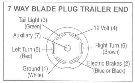
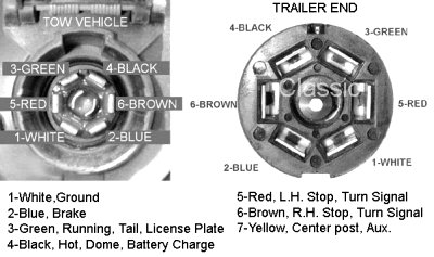
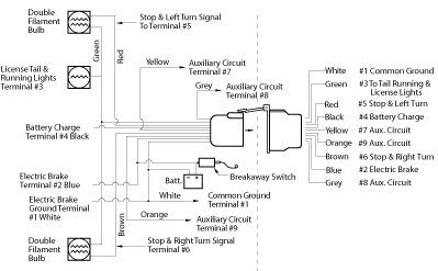
Pole Travel Trailer Connector Wiring Color Code

Way 7 Pole Rv Travel Trailer Connector Wiring Color Code.
Trailer Wiring Diagrams Johnson Trailer Sales Colfax Wisconsin.

Trailer Wiring Sop.

Trailer Light Wiring Typical Trailer Light Wiring Diagram.

Trailer Wiring.
Troubleshooting Trailer Wiring.

For A Trailer Plug And Tow Bar Socket Wiring Diagram.

Http Www Tridenttrailers Com Trailer Wiring Diagram Htm For Britain.

Trailer Wiring.
Trailer Wiring Diagrams Johnson Trailer Sales Colfax Wisconsin.
Trailer Wiring Testers

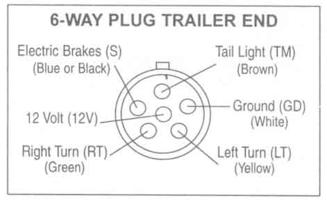
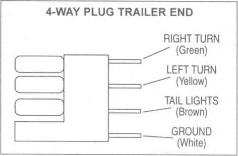
Trailer Wiring Connector Diagrams For 6 7 Conductor Plugs.

Trailer Parts Depot Trailer Wiring Kits Trailer Parts.

Trailer Wiring Testers 1 Jpg.

Trailer Wiring Electrical Connections Are Used On Car Boat And.
Possible Http Www Accessconnect Com Trailer Wiring Diagram Htm.

Trailer Wiring Accessories.

Good Trailer Brake Wiring Harness.

Pin Trailer Wiring Diagram Www Goosenecktrailerparts Com.

Trailer Wiring Diagram Trailer Wiring Troubleshooting Trailer Wiring.
Electric Trailer Brake Wiring Parts Diagrams.
Ethernet Phone Jack Single Cat5e Cablemavromatic
Peak Electronic Design Limited Ethernet Wiring Diagrams Patch.

Cat5e Wiring.
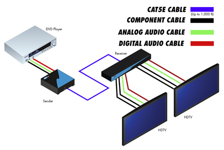
Gefen Component Audio Over Cat5 Wiring Diagram.

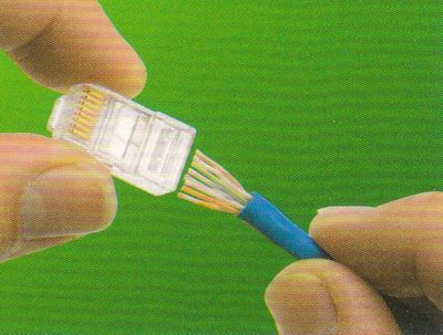
Terminating Rj 45 Cat5 Cat5e Cat6 Data.

An Ethernet And Phone Jack Using A Single Cat5e Cable Mavromatic.

Wiring Diagram For An Ethernet Crossover Cable.
Cat 5 Wiring Diagram Crossover Cable Diagram.

Structured Wiring Retro Install 1.

Cat 5 Wiring Diagram Crossover Cable Diagram.

Rj45 Pinout Wiring How To Make Up A 10baset 100baset Connection Eia.
Tuesday 4 June 2013
Fuse Box Diagram Mercedes W124 ETM 1986-1992


Fuse Panel Layout Diagram Parts: Power Seat Relay, Headlamp Washer
Relay, Auxiliary Fan Relay, Power Window Relay, Auxiliary Fan,
Preresistor Relay, Air Injection Relay, Convenience Relay, Auxiliary
Fuse Holder
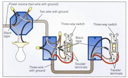
Installing Light Switch

Wiring Diagram 3 If However You Want To Locate The.
Two Way Light Switch Wiring.

Light Switch Wiring Diagram.

Power At Light 4 Way Switch Wiring Diagram.

Neuronetworks Two Way Switch.

Light Fixtures How Three Way Switches Work Garbage Disposal Wiring.
Two Way Light Switch Wiring.
Power Light Switch Switch.

Installing A New Light And Switch.
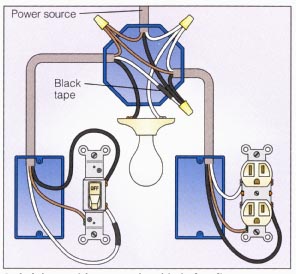
Light And Outlet 2 Way Switch Wiring Diagram.
Overnite Electric Supply Cooper Wiring Devices Details

Cooper Wiring Devices Conduit Accessories Bodies Condulets Unilets.

Overnite Electric Supply Cwd Cr15 Bk Cooper Wiring Devices Details.

Cooper Wiring Devices Rfwc5sg Aspire Rf 5 Button Scene Control Keypad.

Cooper Wiring Devices 309 Cwl1420r Uneedit.

Cooper Wiring Devices 32b 50a Flush Mount Range Receptacle Az.

Cooper Wiring Devices Introduces Mediasync Line Of Innovative Home.

Cooper Wiring Devices Tr274w 3 Wire Receptacle Combo Single Pole.

Cooper Wiring Devices S80 Sp L Commercial Grade Angle Universal Power.

Overnite Electric Supply Cwd 270 V Cooper Wiring Devices Details.

Cooper Wiring Devices L620r 20 Amp 250 Volt Hart Lock Industrial Grade.
Subscribe to:
Posts (Atom)