Monday, 25 March 2013
Amplifier Timer Circuit Diagram

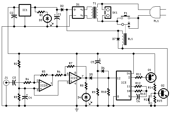
This circuit turns-off an amplifier or any other device when a low level audio signal fed to its input is absent for 15 minutes at least. Pushing P1 the device is switched-on feeding any appliance connected to SK1. Input audio signal is boosted and squared by IC2A & IC2B and monitored by LED D4.
When D4 illuminates, albeit for any fairly short peak, IC3 is reset and restarts its counting. Pin 2 of IC3 is still at the low state, the two transistors seem like on too as the relay operates. When, after a 15 minutes delay, no signal appeared at the input, IC3 ends its counting and pin 2 will go high. Q1 & Q2 stop conducting too as the relay switches-off. The device is thus totally off too seem like the appliances connected to SK1. C5 & R9 reset IC3 at power-on. P2 allows switch-off at any moment.
When D4 illuminates, albeit for any fairly short peak, IC3 is reset and restarts its counting. Pin 2 of IC3 is still at the low state, the two transistors seem like on too as the relay operates. When, after a 15 minutes delay, no signal appeared at the input, IC3 ends its counting and pin 2 will go high. Q1 & Q2 stop conducting too as the relay switches-off. The device is thus totally off too seem like the appliances connected to SK1. C5 & R9 reset IC3 at power-on. P2 allows switch-off at any moment.
Subscribe to:
Post Comments (Atom)
No comments:
Post a Comment
Note: only a member of this blog may post a comment.